In cleanroom design and construction, precision and efficiency are critical to ensuring a safe, controlled environment that meets regulatory requirements.
Faced with these challenges, BIM has established itself as a transformative working methodology within the industry, helping to optimise processes and provide the comprehensive level of control that is essential to the success of these projects. It is emerging as a real game changer for the sector.
BIM tools provide much more than a design platform. They enable us to build a Digital Twin of the project covering every stage, from the initial proposal and detailed design through to construction monitoring and facility maintenance throughout its operational life. This Digital Twin is a virtual replica that allows us to simulate and coordinate the different disciplines before construction begins, reducing risks and costs while ensuring compliance with the highest quality standards, GEP (Good Engineering Practices) and regulatory requirements.
In this article, we explore how Revit, together with Stabicad, Dynamo and other BIM software, improves the accuracy, reliability and agility of our cleanroom projects.
1. Proposal / Basic Design Phase
Every new project begins with the pre-design and/or basic design phase. This is a crucial part of preparing our proposals, as our BIM team needs to be able to generate designs quickly and evaluate different MEP scenarios.
Revit, our standard design software, provides the foundation, but our workflow goes further. By integrating Stabicad, we can rapidly develop initial MEP designs, enabling our designers to outline and visualise the basic routing and configuration of their systems.
Two Stabicad tools are particularly valuable at this stage: Solve Node, as well as its calculation and sizing capabilities.
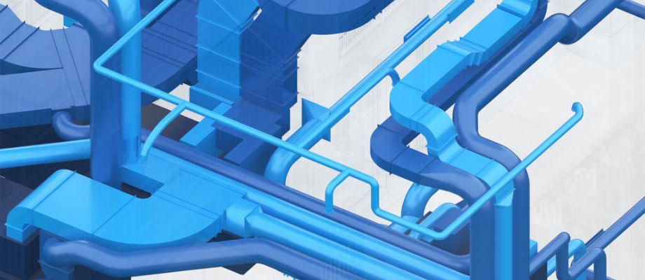
[Fig. 1. Ductwork Design. “General view of the ductwork layout for a project”]
Calculations and Sizing: Systems at the Proposal Stage
Our team of designers and engineers follows a BIM-based approach, working collaboratively to achieve the best possible results.
- Revit provides a solid foundation.
- Stabicad streamlines 3D modelling and calculations.
- Dynamo automates complex processes.
These tools support our decision-making processes, as well as the calculation and sizing of building services.
During the initial design phase, Stabicad allows us to model the elements required to determine the dimensions of return air risers and main ductwork, enabling us to produce an initial estimate of materials and systems. A single element can be used to represent a branch, a space, a level or even an entire building. This makes it possible to quickly determine the space requirements for systems such as ductwork and coordinate them with the cleanroom architecture and other building services in terms of space allocation. In addition, if changes arise at a later stage, the design can be adapted quickly without having to modify a large number of detailed elements.
Being able to visualise everything within a single environment and 3D model is essential. It gives us a clear understanding of how the available space is being used and enables us to prepare a range of graphical presentations that give our clients a clearer understanding of the proposed design.
It also allows us to develop an initial MEP design that lays the groundwork for effective project execution, identifies potential future challenges, helps plan the coordination process and provides a preliminary estimate of the proposed system in terms of size, performance and cost.
“Solve Node”
The “Solve Node” and “Solve Node with Options” functions in Trimble’s Stabicad software are particularly valuable in our projects. Used during the early stages of a project and throughout the design process, these node-solving tools simplify and automate the detailing of complex interfaces and connections within MEP systems.
The “Solve Node” command streamlines, connects and optimises ductwork and piping systems. In our projects, it automatically connects ducts to air terminals, ducts to other ducts and ducts to equipment, significantly reducing the time required to manually create a seamless ductwork layout.
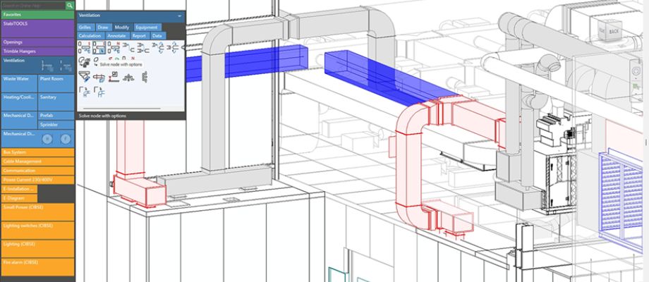
[Fig. 2. “Solve Node” Function. “Example of the function being used to resolve a ductwork connection.”]
The function:
Rotates air terminals where necessary and adjusts connecting ductwork according to the design parameters.
Places flexible and rigid ducts at the appropriate lengths.
Automatically adds components such as VCDs (Volume Control Dampers) and coupling connectors.
By ensuring that all connections are accurate and comply with manufacturers’ specifications, the function helps standardise the work of our design and engineering teams. Its ease of use reduces errors and rework, making the design process more efficient.
While the automatic “Solve Node” command is highly effective for general applications, Stabicad’s “Solve Node with Options” command gives us even greater flexibility and control, providing more precise solutions that can be tailored to specific project requirements.
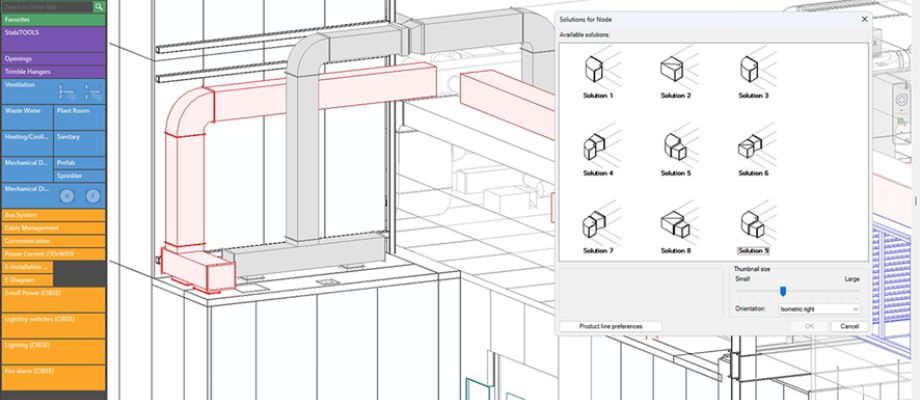 [Fig. 3. “Solve Node” Options. “The ‘Solve Node’ function provides different options, allowing designers to select the most appropriate solution for the design.”]
The “Solve Node with Options” function is particularly useful for managing complex design constraints in Revit, automatically suggesting multiple connection options for ductwork and piping systems. It allows designers to select the most appropriate solution based on the required angles and fitting types, helping to overcome design challenges while maintaining the right balance between control, automation and customisation.
The command can be applied to specific nodes or sections, enabling complex projects to be managed efficiently by focusing only on areas that require particular attention without affecting the entire system.
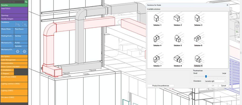 [Fig. 4. “Solve Node” Solution. “Stabicad automatically generates the required components based on the selected option.”]
Data Extraction and Transformation Process for Proposals
Dynamo enables process automation through visual programming, helping to optimise tasks automatically. As an example, we present one of the processes we have developed and automated to extract data from HVAC system ductwork modelled in Revit. This process is implemented through a Dynamo routine integrated with a dynamic Excel spreadsheet, making it easier to integrate and convert the extracted data into accurate quantity take-offs in compliance with the applicable national regulations.
The methodology applied ensures that the quantities accurately reflect the project requirements, taking into account, among other factors, material waste that Revit is unable to anticipate. This method is also consistent with the practices of our regular material supplier, ensuring a more accurate proposal phase that better reflects actual supply and material usage conditions.
The following image shows how the process works with a parametric component. In this case, Revit is unable to calculate the total area; however, our routine enables us to export the data to our spreadsheet.
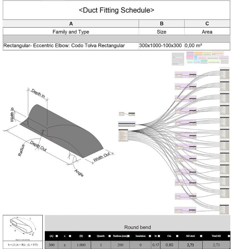
[Fig. 5. Dynamo Routine. “Example of the data extraction routine developed.”]
2. Detailed Design Phase
Once our proposal has been accepted by the client, the project moves into the next stage of development. Wherever possible, we build on the approved basic design and optimise it to produce a detailed design for the entire facility. At this stage, we consider all the parties and factors involved, from suppliers and coordination with other design disciplines to maintenance requirements and specific solutions that need to be taken into account during installation, ensuring that every aspect of the design meets the established quality and efficiency standards.
Our engineering team focuses on the details, adjusting and refining each component within the system to develop a customised design that meets the specific requirements of each production process within the cleanrooms while also complying with the applicable regulations.
At this stage, accuracy, efficiency and modelling tools are essential for the engineering team. Stabicad provides accurate and reliable calculations, automated system sizing and comprehensive documentation capabilities. This helps ensure that the detailed MEP design is accurate, efficient and fully coordinated, while meeting the required quality standards.
Two of Stabicad’s key functions at this stage are “Calculations” and “Sizing” of MEP systems within Revit. Together, they help ensure that MEP systems are correctly sized and deliver optimal performance while complying with industry standards and project requirements.
Thanks to the flexibility of the software, we can easily adapt the design and dimensions of the ductwork and visualise the impact of critical design decisions, while automatically checking the system against the relevant engineering calculations.
At this stage, another key feature provided by Stabicad is its extensive content library. It includes dimensionally accurate components, as well as product and technical data based on manufacturers’ catalogues. Connector positions, overall dimensions and service clearance information are aligned with the manufacturers’ specifications, providing confidence that the model can actually be built as designed. Combined with the “Solve Node” functionality described above, this allows us to quickly select the appropriate content for each project and connect the system using fittings and equipment that are genuinely buildable.
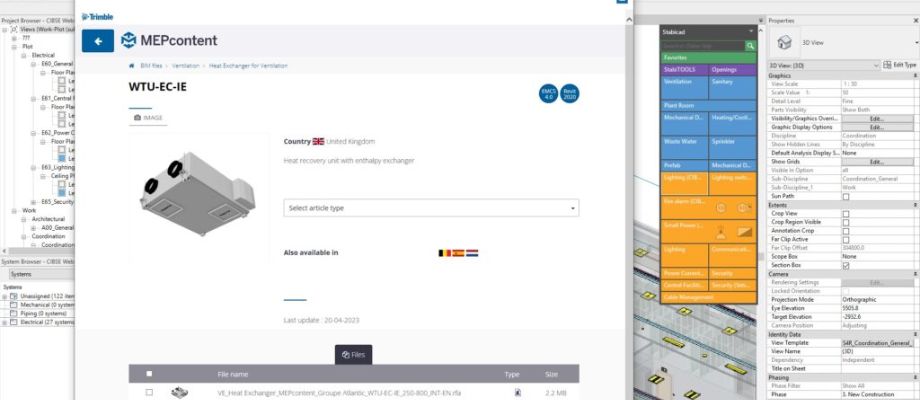 [Fig. 6. MEP Content. “Stabicad platform featuring pre-built manufacturer families, ready to be used for optimised calculations.”]
Calculations are crucial for correctly determining the capacity and sizing of HVAC system components.
For ductwork and piping systems, Stabicad can automatically calculate flow rates, velocities and pressure drops. This helps us select the appropriate system sizes to ensure efficient performance and avoid excessive energy consumption. It also allows us to define specific design criteria such as sizing parameters, shape, length, width and maximum diameter, as well as maximum and minimum velocities and maximum pressure drop per metre. The calculation then automatically identifies the smallest available size that meets all the specified criteria and applies it directly to the 3D model.
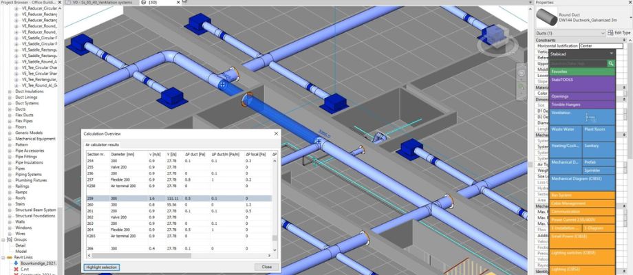
[Fig. 7. Ductwork Calculation. “Example of ductwork calculation results generated using Stabicad.”]
The software supports multiple standards across different European countries, making it particularly well suited to international projects. For UK standards, the calculations are even CIBSE-certified, providing an additional level of assurance in terms of accuracy and reliability.
However, one of the software’s main advantages for us is its ability to automatically update calculations and system sizes as changes are made to the design. This dynamic capability gives us confidence that the design will remain accurate and up to date, even as modifications are introduced.
For our design team, Stabicad provides flexibility, control and the ability to create detailed, accurate MEP designs that are ready for construction. Working in 3D allows us to view everything within a single model, explore complex interfaces between MEP elements and understand the impact of our design decisions. It also improves collaboration and communication with clients by allowing us to present our proposed MEP design in 3D, something that was more difficult to achieve with traditional 2D drawings.
Another highly valuable tool during this phase is Dalux. This platform allows us to involve all project stakeholders from the outset, both internal — Project Managers, Site Managers and designers — and external, including the client, suppliers and the other disciplines involved in the project.
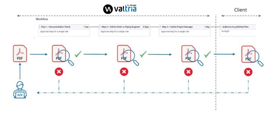
[Fig. 8. Company–Client Communication Diagram. “Diagram showing how internal and external communication is managed through Dalux.”]
This platform allows us to keep all technical information, the BIM model and graphical documentation in a single location, while also bringing together internal and external communication channels, including emails and meetings. This streamlines the workflow, allowing the client to focus on reviewing and approving the project and verifying that the proposed design meets their requirements.
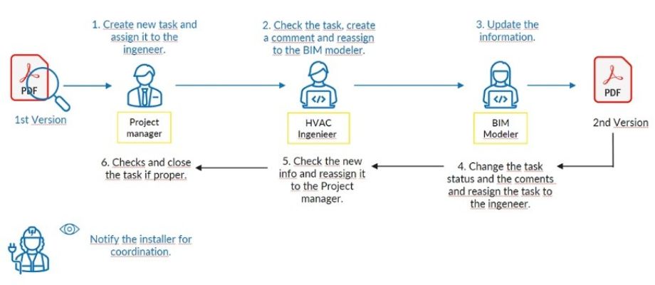
[Fig. 9. Internal Approval Process Diagram. “Example of the internal communication workflow through to version approval.”]
For internal communication, Dalux enables the Valtria team to prioritise tasks, delegate responsibilities and streamline the review process. Its colour-coding system makes it easy to identify the status of each task at a glance.
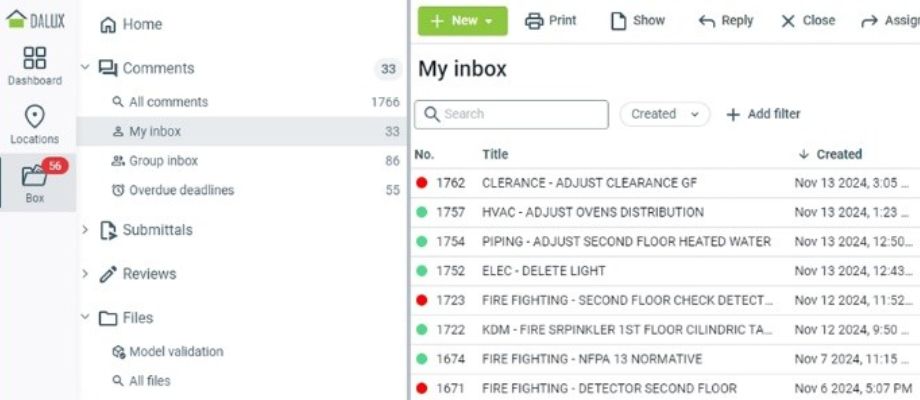
[Fig. 10. Tasks. “Project task view showing the colours associated with each task status.”]
The advantages of using a range of complementary BIM tools, such as Revit, Stabicad, Dalux and Dynamo, during the design phase create synergies that enhance the capabilities of each platform. This integration helps us optimise both the efficiency and quality of our projects.
3. Construction Phase
The final stage of our journey usually takes us to the construction phase, where we continue to leverage the synergies between our core BIM tools, including Revit, Stabicad and Dalux. At this stage, continuously updating our Digital Twin becomes essential. Each adjustment and modification brings us one step closer to the final objective, ensuring that every detail remains under control.
With Dalux, site teams can access project documentation directly from the construction site, while also digitising quality control, inspection and commissioning procedures through the mobile application.
Making information readily accessible to everyone involved promotes seamless communication between the different teams working on site and in the office.
[Fig. 11. Dalux Project Interface. “Project navigation screen in Dalux.”]
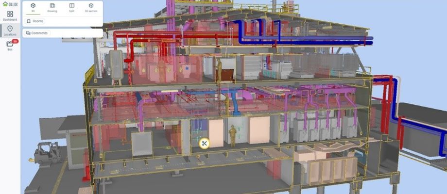
Dalux contains the digital model and project information, providing each team member with the tools relevant to their specific role as part of a real-time, BIM-based collaborative workflow that remains available even without an internet connection.
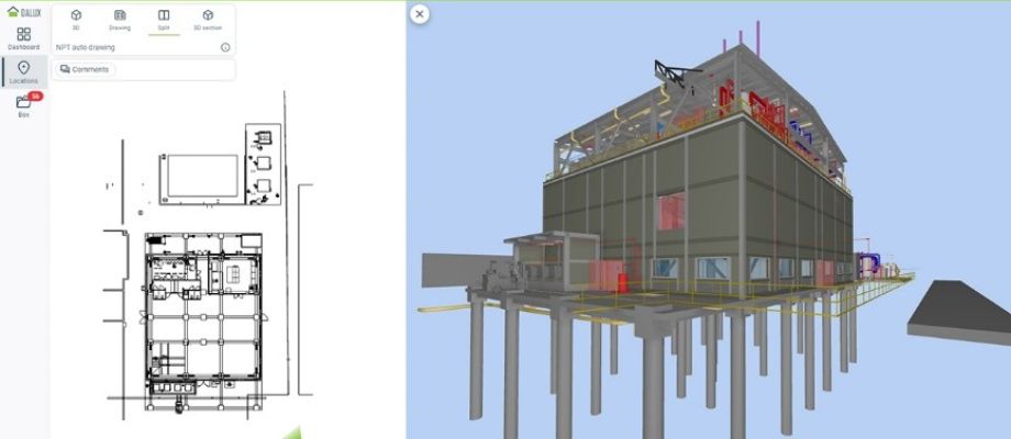
[Fig. 12. Example View. “Combination of the 3D model and 2D information in Dalux.”]
With the collaboration of our entire team — Site Managers, Project Managers, the Design Team and others — we ensure that the project progresses smoothly, reflecting our commitment to precision and quality. We complete the process with the satisfaction of turning a vision into reality.
4. Operations Phase
Finally, throughout the operational life of the facility, we recommend that our clients keep the Digital Twin up to date and use it as a reference for cleanroom monitoring and maintenance. When required by the client, we implement these solutions using the same software tools employed during the construction phase, including Dalux.
Dalux, in particular, facilitates the management and tracking of maintenance tasks, enabling efficient and accurate monitoring of all activities. For example, QR codes can be added to equipment, providing quick and easy access to relevant information simply by scanning the code.
In addition to all the information incorporated into the model during the previous phases, the platform can also provide access to the control systems associated with our cleanrooms. Maintenance technicians can receive alerts directly on their mobile devices, helping them optimise their work, identify equipment and organise spare parts or materials more efficiently. This approach helps ensure that the cleanroom remains in optimal operating condition while meeting the established quality and efficiency standards.
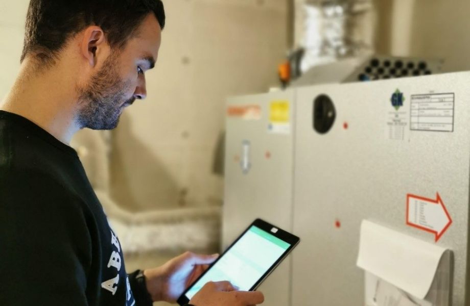
[Fig. 13. Maintenance Technician. “Dalux provides access to the data stored in the model required for the effective maintenance and operation of the project.”]
Conclusion
The implementation of BIM tools throughout every stage of a cleanroom project lifecycle not only supports design and construction but also optimises communication and coordination between teams, while helping to meet client standards and expectations. This approach allows each project’s Digital Twin to evolve alongside the project itself, providing an invaluable resource for the future maintenance and management of the facility. By integrating Revit, Stabicad, Dynamo and other applications, we achieve an efficient workflow that complies with applicable standards and offers the flexibility required to improve overall project performance and the quality of the final outcome.
Abbreviations and References
- BIM: Building Information Modeling
- MEP: Mechanical, Electrical, and Plumbing
- VCD: Volume Control Damper
- HVAC: Heating, Ventilation, and Air Conditioning
- ISO 19650: International standard for managing information throughout the lifecycle of a built asset.
- Stabicad: Stabicad for Revit is a powerful BIM solution for mechanical and electrical design. https://mep.trimble.com/en/products/stabicad
- Dynamo: Dynamo is a visual programming tool used to automate tasks and processes within BIM software such as Revit. https://dynamobim.org/
- Dalux: Project management software. https://www.dalux.com/